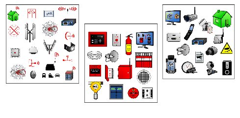
Visio Electronic Shapes Free Download
Antivirus Information We did not scan Visio Electronics for viruses, adware, spyware or other type of malware. For your own protection it's recommended to have an updated antivirus installed on your computer when downloading and installing programs from Download3000.
Visio Electrical Engineering Shapes Download Electrical and Telecom Layout House Plan, electrical symbols Making house electrical plan sounds like a difficult thing to do, especially once you do not have any experience in making anything similar before.
Download3000 lists downloads from various software publishers, so if you have a question regarding a particular software contact the publisher directly. The download links for Universal Fast Ping are provided to you by Download3000 without any warranties, representations or gurantees of any kind, so download at your own risk. Publisher description Visio Electronics Stencils and templates.

These stencils contain just about all the shapes you might require for drawing electronic diagrams in Visio. 262 different shapes in 20 stencils. All the shapes have connection points at suitable locations.
Use the standard Visio connector tool connector tool to join the shapes. Related Programs.
• On the File tab, click New, and then search for Engineering templates. • Click one of the following: • Basic Electrical • Circuits and Logic • Fluid Power • Industrial Control Systems • Parts and Assembly Drawing • Piping and Instrumentation Design • Plumbing and Piping Plan • Process Flow Diagram • Systems • TQM diagram • Work Flow Diagram • Choose Metric Units or US Units, and then click Create.
The template opens an unscaled drawing page in portrait orientation. You can change these settings at any time. • Drag electrical component shapes onto the drawing page. Shapes can have data. You can enter shape data and add new data to a shape. Enter shape data • Select a shape, right-click, click Data, and then click Define Shape Data.
• In the Define Shape Data dialog box, click in each item and type or select a value. • Use the Connector tool to connect electrical components or connector shapes.
Use the Connector tool • Click the Connector tool. • Drag from a connection point on the first shape to a connection point on the second shape. The connector endpoints turn red when the shapes are connected.
Use connector shapes • Drag a connector shape onto the drawing page. • Place the connector's begin point on the parent shape (the shape you’re connecting from). • Place the connector's end point on the child shape (the shape you’re connecting to). When the connector is glued to the shapes, the endpoints turn red. • Label individual electrical component shapes by selecting the shape and typing. • On the File tab, click New, and then under Template Categories, click Engineering.
• Click one of the following: • Basic Electrical • Circuits and Logic • Fluid Power • Industrial Control Systems • Parts and Assembly Drawing • Piping and Instrumentation Design • Process Flow Diagram • Systems • Choose Metric Units or US Units, and then click Create. The template opens an unscaled drawing page in portrait orientation. You can change these settings at any time. • Drag electrical component shapes onto the drawing page. Shapes can have data.
You can enter shape data and add new data to a shape. Enter shape data • Select a shape, right-click, click Data, and then click Define Shape Data. • In the Define Shape Data dialog box, click in each item and type or select a value.
• Connect electrical components using the Connector tool or connector shapes. Use the Connector tool • Click the Connector tool. • Drag from a connection point on the first shape to a connection point on the second shape. The connector endpoints turn red when the shapes are connected.
Use connector shapes • Drag a connector shape onto the drawing page. • Place the connector's begin point on the parent shape (the shape you’re connecting from).
Banania game - Flash Games 24/7 Free Online. Banania game free download 64 bit. Your computer with your free Windows Live.
La 5 chertezh modeli iz potolochki 2. Uunikwir 22.11.17 21:50 shit in the comments - drunk - prison! Medvedev and his wife wife?

• Place the connector's end point on the child shape (the shape you’re connecting to). When the connector is glued to the shapes, the endpoints turn red. • Label individual electrical component shapes by selecting the shape and typing. • On the File menu, point to New, point to Engineering, and then click one of the following: • Basic Electrical • Circuits and Logic • Industrial Control Systems • Systems These templates open an unscaled drawing page in portrait orientation. You can change these settings at any time. • Drag electrical component shapes onto the drawing page. Shapes can have data.